What is (HF) High Frequency?
High Frequency (HF) is a frequency band within the Radio Frequency Wave Bands (RF). HF is band Number 7 in the ITU (International Telecommunication Union) numbering sequence.
High Frequency (HF) Band is between 3 – 30 MHz
Below HF frequency is (MF) Middle frequency band No 6 (MF) 300 – 3000 KHz
Above HF frequency is (VHF) Very High Frequency band No 8 (VHF) 30 – 300 MHz
These days most High Frequency plastic welding equipment operates at 27.12 MHz
How does HF weld plastics?
The (HF) High Frequency waves are produced in the machine’s generator and travels via tuned copper feed straps to the welding tool. Between the welding tool and machine lower platen you have the product(s) that requires bonding together. This is normally PVC (Polyvinyl chloride) material, although other material can also be HF welded such as PU, A PET, and PET G.
As HF waves travel through the PVC material into the lower platen the molecules in the PVC material are agitated and start to produce heat, the heat reaches a point where the polymer in the material starts to soften. The downwards pressure exerted on the welding tool by the machine press forces the molten PVC to bond together, the HF is then switched off but the machine press continues to apply pressure until the molten PVC solidifies. The press then opens, leaving behind the layers of PVC completely fused together creating a strong bond.
How do I achieve an optimal weld?
Achieving the optimal weld depends on the welding equipment, product material and weld surface area. Below are some factors and parameters to consider:
- Welding equipment output power: as a basic rule welding equipment will weld 22.5cm2 per 1 kilowatt of HF energy produced. As you increase the weld area the more kilowatts of HF energy are required.
- Welding press pressure: a pneumatic operated welding press will operate between 2 – 6 bars of pressure. A foot operated mechanical press will apply a maximum of 2.5 bar of pressure. The larger the weld surface area the greater the pressure required. On extremely large areas the welding press would be hydraulically operated.
- Delay time: this is the time that it takes to close the welding press on the product and reach its full operating pressure. Some welding tools are pre-heated to allow additional softening of the PVC material prior to the HF welding process, in this case the delay time would be set to a longer duration.
- Weld time: the weld time controls how long the HF energy is applied. As previously explained the HF welding process on average will take 3 – 6 seconds of weld time to fuse the PVC layers together, this will vary depending on the number of layers and the thickness of the material. On heavy duty material weld times can be up to 20+ seconds.
- Cool time: once the HF energy stops, the welding press will remain under pressure for the duration of the cool time to allow the welded area to solidify. Again this will vary depending on material, although as a general rule we find the cool time is normally set to 50% of the weld time.
- Output power: the output power is controlled by variable plates in the generator. The generator is designed and rated to an output value, this is measured in kilowatts. Smaller single phase generators are rated between 0.5 kW to 2 kW. Three phase generators will be rated from 3 kW upwards. The power requirement and settings will again depend on the tool surface weld area and the product material (this is referred to as the load). When setting the output power position, the variable capacitor plates in the generator are adjusted to match the capacitance of the load. Once this is achieved the correct amount of HF energy will be flowing from the generator through the product into the lower platen and back to generator via the earth return path. If there are any unnecessary resistances, or mismatch of load, this will result in poor weld quality.
- Barrier material: this is used to prevent the HF waves from travelling directly into the lower aluminium platen during the weld cycle and causing an arc / flash. There are a number of different types of barrier materials for different applications. The barrier material can also help to retain heat and energy in the product during the weld cycle which will help in the bonding process.
Suggested parameters / settings
Once you have selected the correct type of equipment for your plastic welding process, start with the following parameters as a guide:
| Stage | Time |
| Pre-weld time | 2 seconds |
| Weld time | 4 seconds |
| Cool time | 2 seconds |
| Output | 10% |
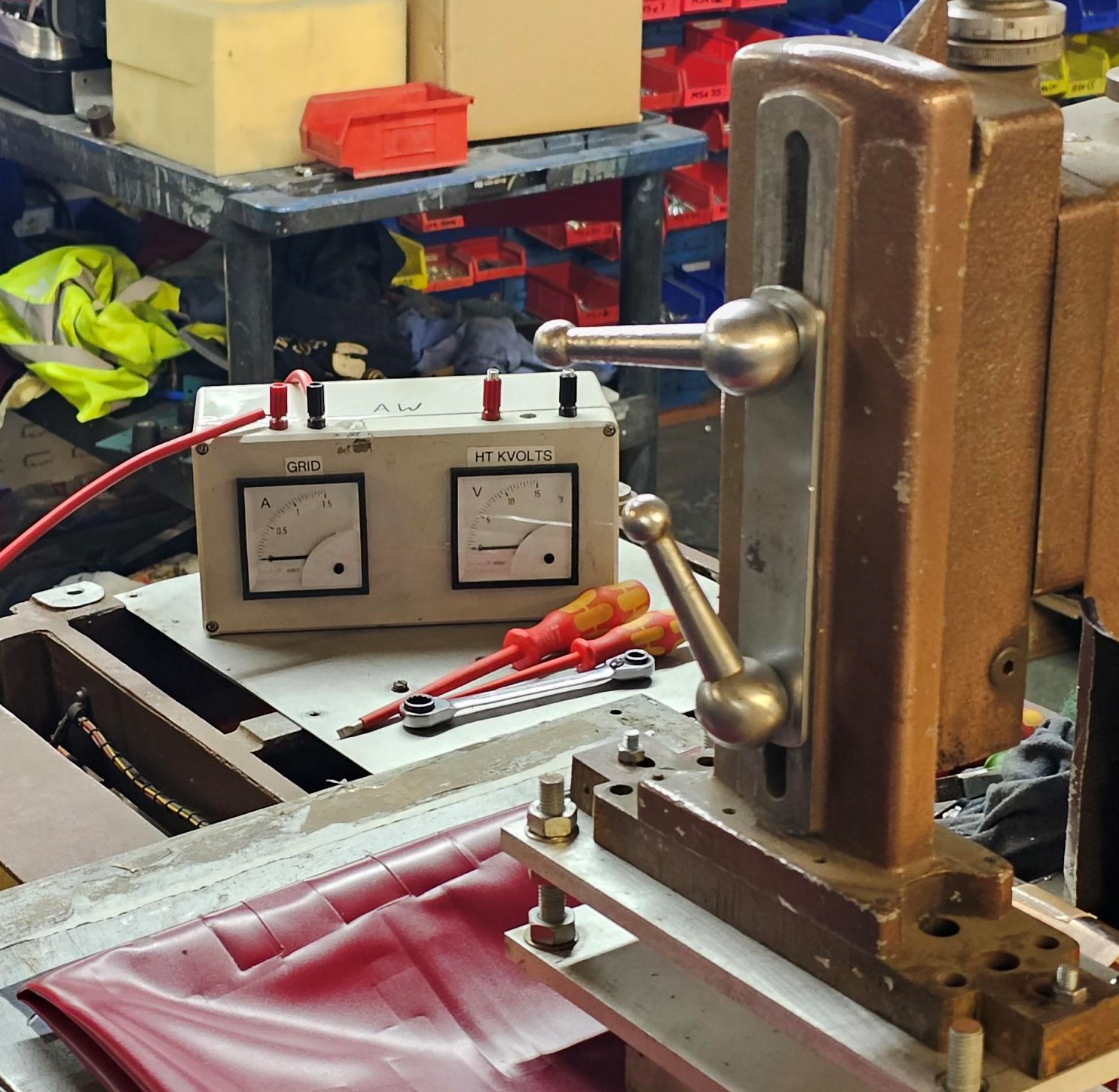
During the weld time you are looking for the output meter to climb gradually and then stop as the product material softens and starts bonding. After the initial stop of the output meter it should drop back slightly. If you did not achieve this then increase the output power. If the output meter starts to climb rapidly and continues increasing then reduce the output power and increase the weld time.
There are no hard or fixed settings for a particular product. You are looking for a balance between output power and weld time. You may achieve similar results with high output power and short weld time, or low output power and a long weld time.
It is best to have a longer weld time and less output power where possible. This will reduce arcing/burning resulting in down time. Less output power will also help to prolong the life of the oscillator valve which produces the High Frequency energy in the generator.


